

05.11.2026 - 08:00:00
The Joint Is the System, Part 2: The Insulation Is in the Duct
A factory-built zero-clearance grease duct carries its insulation inside the duct, section by section. The rating is decided at the thirty or forty joints where those sections meet.
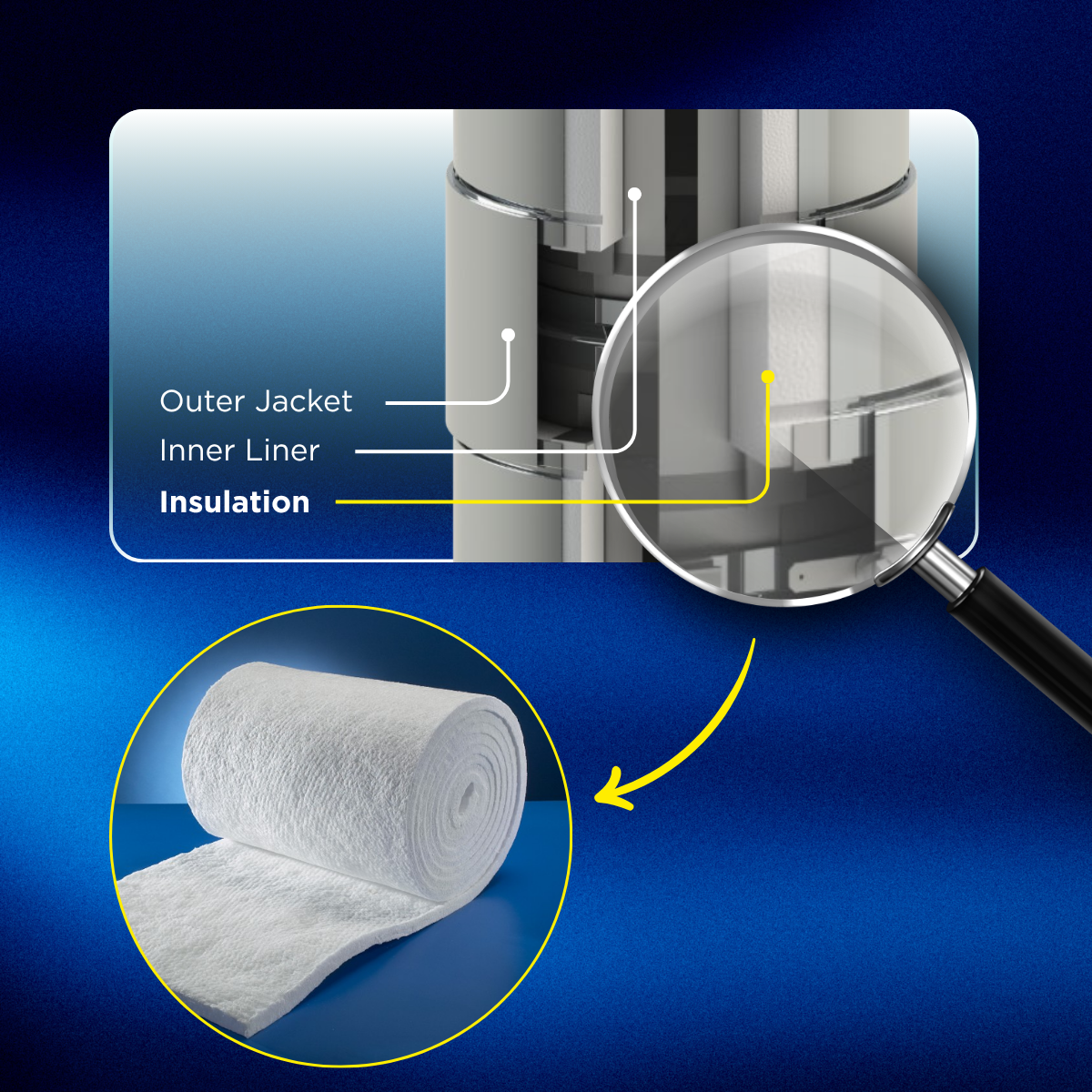
Cut a section through a double-wall grease duct on a detail sheet and it shows three concentric things: an inner liner, a band of insulation, an outer jacket. The hatch pattern for the insulation runs unbroken from one edge of the detail to the other.
On the loading dock it looks different. Each section arrives with its insulation installed and its jacket closed, and each section’s insulation stops short of the inner connection, because someone has to reach that connection to make it. Thirty or forty sections. Thirty or forty places where the factory’s work ends.
Part 1 of this series, The Joint Is the System, argued that containment, pressure, alignment and slope in a commercial kitchen exhaust system are all decided where two sections meet, and that the sections should engage in steel before the seal is loaded. This one stays at the same location and moves outward by an inch or three, into the annulus. The inner connection decides whether grease stays in the duct. What surrounds that connection decides whether the duct can sit where the drawings put it.
Two jobs that share one blanket
The insulation in a double-wall grease duct does two different things, and they are qualified by two different listings.
Clearance.NFPA 96 sets the default at 18 inches to combustible construction, 3 inches to limited-combustible, and zero to noncombustible. A listed factory-built grease duct is permitted to reduce those figures in accordance with its listing, and UL 1978 is where the reduced figure comes from: heat generated inside the duct, at operating temperature and through the 2000°F abnormal exposure, measured for what it does to the construction around it.
Enclosure. Where the codes require the duct to be enclosed (NFPA 96 and the IMC draw that line slightly differently), there are three routes: a rated shaft, a field-applied enclosure material tested to ASTM E2336, or a factory-built assembly listed to UL 2221. That last standard asks a harder question than clearance. It exposes the assembly to fire from the inside and from the outside, and asks whether the duct can stand in for the shaft.
In a zero-clearance product the same blanket does both jobs, which is why the two get merged in spec sections. A system can carry a reduced-clearance listing under UL 1978 without being an enclosure under UL 2221, and a section that asks for one has not asked for the other.
Thickness is not the specification
The Jeremias DWFL family makes the point cleanly, because it is one liner and one joint offered across six wall-space configurations:
- DWFL: 1.25-inch air space
- DWFL+1: 1.25-inch insulated wall space
- DWFL+2: 2.25 inches
- DWFL+3: 3.25 inches
- DWFL+4: 4.25 inches
- DWFL-ZC: 3.25 inches, listed to UL 2221
Compare DWFL+3 and DWFL-ZC. The thickness is identical. What differs is what the assembly was tested as: DWFL-ZC is the configuration manufactured to achieve the UL 2221 two-hour fire-resistive enclosure rating at zero clearance. A spec section that reads “minimum 3 inches ceramic fiber insulation” is satisfied by both and has described only one of them.
Two practical consequences follow. First, the configurations may be intermixed in the same system, so the insulation can follow the requirement along the run instead of being set everywhere by its most demanding segment.
Second, insulation is weight. At 24 inches inside diameter, the DWFL/SWFL submittal record puts DWFL+1 at 26.4 pounds per foot and DWFL-ZC at 42.7. That is a structural number, and it belongs on the support drawings before it belongs anywhere else.
For grease duct specifically, the DWCK line follows the same logic. DWCK+1 is listed to UL 1978 for reduced clearance. DWCK-ZC is listed to both UL 1978 and UL 2221.
Compressed, not just installed
Those figures are the wall space. The blanket that goes into it is thicker. In the Jeremias round double-wall lines (AF, CK, KL and FL), the insulation is compressed into its space:
- +1: 1.5-inch blanket compressed into a 1.25-inch space
- +2: 2.5-inch blanket compressed into a 2.25-inch space
- +3: 3.5-inch blanket compressed into a 3.25-inch space
- +4: 4.5-inch blanket compressed into a 4.25-inch space
The common alternative in the industry is a blanket at the same nominal thickness as the wall space. It is easy to fabricate, because the blanket slides straight in. It is also held in place by nothing. Shipping, handling and vibration do the rest, and the blanket settles toward the bottom of the annulus. Jeremias has opened other manufacturers’ duct on site and found as much as six inches of empty air space where the insulation had fallen away in transit. That section still has its label. It no longer has the wall it was listed with.
Compression does two things a loose blanket cannot.
It stays where the factory put it. A blanket under compression does not migrate in a truck, on a forklift, or over years of thermal cycling.
It holds the walls concentric. The compressed blanket bears evenly on the liner and the jacket, so the wall space stays uniform all the way around the section.
The same construction runs through the Jeremias boiler stack and engine exhaust lines, where it shows up as a smaller outside diameter for a given skin temperature and clearance. For grease duct, the point is simpler: the insulation the listing describes is the insulation that arrives on site.
Every section ends
Here is the condition every factory-built double-wall system shares, whoever made it. Three things happen at the joint that happen nowhere else along the run.
The metal reaches outward. The hardware that makes the inner connection, whether a flange, a band, or a clamp, stands proud of the liner into the annulus. It is the one place where hot steel sits closer to the jacket than the typical section shows.
The insulation changes hands. Everything between the joints was cut, fitted and closed under factory conditions. What goes into the joint cavity is installed overhead, off a lift, by the crew making the connection.
The jacket is interrupted. The outer wall is what keeps the blanket in position, dry, and out of reach of the next trade on the job. At the joint, a separate closure has to pick that job up.
None of this is a defect. It is what modular construction is. But it means the figure on the listing is a statement about the joint as much as about the section, because the assembly that went into the furnace had joints in it, closed with specific components in a specific sequence. The joint insulation is a listed part of the assembly. It is not packing.
Engage, seal, then close
On the flagship DWFL systems the joint goes together in three steps, and the order is the same every time.
- The inner connection is made and sealed. The sections engage across a 1.25-inch overlapping inner and the half-inch rolled flanges meet. Sealant goes on in two places: on the flange faces before they are joined, and in the groove of the vee band before it is drawn tight. This is the joint Part 1 described.
- The joint insulation goes on. The supplied blanket is wrapped around the vee band, filling the cavity between the factory-insulated ends.
- The outer band closes it. The locking band is positioned over the joint and tightened. It ships attached to each part and closes with an integrated worm gear, so there is no loose hardware to carry up the lift or leave off. Indoors, the band is not caulked. Only on exterior runs is the top of the band caulked against weather.
Three things about that sequence deserve an engineer’s attention.
The first is the material. The joint is finished in blanket insulation supplied with the system, not whatever is on the truck. Jeremias specifies a blanket that contains neither binder nor lubricant, so there is nothing in the annulus to burn off, smoke, or smell the first time the duct sees temperature.
The second is that the inner connection sets up the outer one. Because the liner aligns itself over an inch and a quarter of overlap before anything is tightened, adjacent sections land concentric and flange to flange. The joint cavity is the size the joint insulation was made for. A connection that relies on clamp tension for alignment can leave a cavity that is wide on one side and pinched on the other, and a blanket performs at its installed thickness, not its nominal one.
The third is easy to miss. Fiber blanket is absorbent. A joint that weeps grease into its own insulation is loading the annulus with fuel at the exact location the listing depends on, and nobody sees it until the band comes off. Liquid-tight on the inside is the precondition for everything the insulation is credited with. That is the practical reason the sequence runs engage, seal, then close, and why Part 1 and Part 2 of this series are really a single argument.
Factory-built, field-applied, and the line between them
The codes keep two qualification paths separate, and the separation is worth enforcing in submittal review.
ASTM E2336 qualifies field-applied enclosure material. It is the test for a wrap installed on site around a duct.
UL 2221 qualifies factory-built enclosure assemblies. NFPA 96 and the IMC both require a factory-built grease duct enclosure to be listed to it. Jeremias carries that listing on the DWFL-ZC, DWCK-ZC, and DWCKF-ZC round models, and on the DWGD-RZ rectangular model, which uses 3 inches of insulation.
Some products on the market are offered as factory-built enclosures on the strength of ASTM E2336 testing. That is a field-applied test result attached to a factory-built claim, and it does not meet the code path for a factory-built enclosure. If the submittal for a factory-built system cites ASTM E2336 and not UL 2221, it should stop there.
Field wrap is still a legitimate route, with a condition. NFPA 96 permits a listed factory-built grease duct to be enclosed with field-applied material only where the material and the assembly of duct and material are listed for that application. Jeremias holds that listing. Its reduced-clearance grease ducts can be field-wrapped and keep their listing, across the single-wall SWKL, SWFL and SWCK models and the double-wall DWKL, DWFL and DWCKF models, evaluated through ICC-ES, using three approved ASTM E2336 wraps: Unifrax FyreWrap Elite 1.5, Thermal Ceramics Firemaster FastWrap XL, and 3M Fire Barrier Duct Wrap 615+. On the double-wall reduced-clearance models, one layer of wrap brings the assembly to zero clearance as a UL 2221 enclosure.
That leaves the engineer choosing between two compliant approaches, and the choice comes down to trades and space.
Wrap means an insulation contractor arriving after the duct is hung, and every overlap in the wrap is a field joint in the fire barrier. A factory-built zero-clearance assembly has exactly as many field closures in its insulation as it has duct joints. Each one is identical, and each one is finished by a band that is either on or visibly missing. The Jeremias zero-clearance kitchen system data sheet states the scope plainly: the design eliminates the welding, the second insulation trade, and the third trade for a fire-rated shaft.
Both approaches also change the space a riser takes. Under NFPA 96, a duct inside a noncombustible or limited-combustible shaft needs 6 inches of clearance to the interior of the enclosure. A 16-inch duct therefore needs 28 inches clear inside the shaft before the shaft walls are counted. The same 16-inch duct as DWFL-ZC, with 3.25 inches of insulation, is about 22½ inches in outside diameter and is listed at zero clearance. On a multi-story riser, that difference is floor area on every level.
How to specify the insulated joint
Most double-wall spec sections name a listing and an insulation thickness and leave the joint to be inferred. Five additions close it.
- Name the listing for the job. UL 1978 where the system is relied on for clearance. UL 2221 where it is relied on as a factory-built enclosure. Both where it is doing both. Do not accept ASTM E2336 as the qualification for a factory-built assembly.
- Specify the wall space by model and thickness, and require the blanket to be compressed into it. “Minimum 3 inches of insulation” admits configurations that share a thickness and differ in rating, and it says nothing about whether the blanket will still be there when the duct arrives.
- Require the manufacturer’s listed joint insulation and closure band at every joint. Factory-supplied, installed per the listed instructions. Prohibit field-substituted wrap, loose fill, and omitted bands. With one sentence, the joint cavity stops being left to the installer’s discretion.
- Where field wrap is used, require the wrap and the duct to be listed together. Name the approved wrap products from the duct manufacturer’s listing, not a generic E2336 material.
- Require joint closure to be confirmed before concealment. The leakage test already has to happen before the duct is concealed. Add the outer closure to the same walk: every band present, seated and tight, and caulked only on exterior runs.
The point
A zero-clearance rating is a continuity claim. It says the insulated envelope around the liner is unbroken from the hood to the roof. The place to evaluate that claim is the place it could break.
So, as before, there are two questions worth asking any manufacturer in this category, and both fit in an email:
What goes in the joint cavity, who supplies it, and what holds it there? A material, a source and a mechanical closure answer this. “Installer to insulate joints as required” does not.
Show me the joint in the UL 2221 listing. The listed detail, with the joint insulation and the band in it. The submitted detail should match it exactly.
Jeremias answers the first with blanket insulation supplied with the system, compressed into the section and wrapped over the vee band at the joint, then captured by a locking band that ships attached to the part. It answers the second the way it answers every question of this kind: by publishing the technical data sheets, submittal records, sample specifications and installation instructions openly and ungated.
Engage, seal, then close. In that order, at every joint.
Next in this series
With Jeremias, the insulation is in the duct, and the joint between sections is the one interruption that repeats. The ones that do not repeat are harder: the hood collar, the floor and roof penetrations, the supports that carry 42 pounds a foot through a zero-clearance envelope, the access doors a cleaning crew opens for the life of the building, and the fan at the top. Part 3 of The Joint Is the System follows the insulated envelope to every connection between the duct and the building.
ABOUT JEREMIAS |
Jeremias® Exhaust Systems manufactures all-stainless steel grease duct, chimney, gas vent, and industrial exhaust systems in Marietta, Georgia, serving North America across commercial and industrial segments. German engineering origins, more than fifty years in the venting and exhaust industries, and a global manufacturing network — and now built in the USA.
Every Jeremias connection engages in steel before the seal is loaded, either as a male-to-female overlap or as a full-inside-diameter collar into expanded ends — never a bare butted flange, never a reduced-diameter spigot. The flagship SWFL and DWFL systems pair a 1.25” overlapping inner with a ½” rolled flange and vee band, are UL Listed to 90” W.C. positive internal static pressure, and cover kitchen exhaust duct, chimney and gas vent, engine and CHP exhaust, fume venting, and process stacks in a single product family.
In North America, Jeremias uses Underwriters Laboratories and ICC-ES exclusively for testing, certification, and listings, and has operated its own R&D laboratory in Logan, Ohio since 2013. Grease duct systems ship with factory sizing calculations and CAD installation drawings. Specifying engineers can request a factory session at Jeremias University — product and specification training, system sizing, engineer demonstrations, and a plant tour
— or download technical data sheets, submittal records, and installation manuals directly, with no gate.
Jeremias Inc. · 1255 Kennestone Circle, Suite 150, Marietta, GA 30066 · (678) 388-2740 · info@jeremiasinc.com
Other contents that serve your interests
The Joint Is the System, Part 2: The Insulation Is in the Duct
A factory-built zero-clearance grease duct carries its insulation inside the duct, section by section. The rating is decided at the thirty or forty joints where those sections meet.
Cut a section through a double-wall grease duct on a detail sheet and it shows three concentric things: an inner liner, a band of insulation, an outer jacket. The hatch pattern for the insulation runs unbroken from one edge of the detail to the other.
The Joint Is the System
A grease duct is not one object. It is a few dozen connections in series — and every one of them has to do six jobs at once.
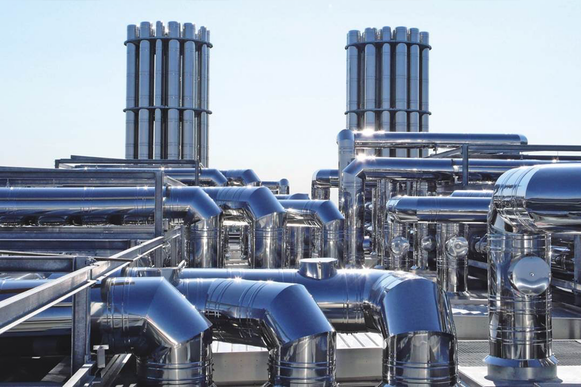
Draw a grease duct on a page and it looks like a single continuous thing: a line running from the hood collar, across the ceiling cavity, up a chase, out through the roof. One element. One line weight. One entry in the schedule.